
|
Red X's in freq boxes - No Comm with VHF |
Post Reply 
|
| Author | |
vas4avidyne 
Groupie 
Joined: 21 Jun 2022 Location: SF Bay Area Status: Offline Points: 50 |
 Post Options Post Options
") Thanks(0) Thanks(0)
 Quote Reply Quote Reply
 Topic: Red X's in freq boxes - No Comm with VHF Topic: Red X's in freq boxes - No Comm with VHFPosted: 22 Jan 2024 at 11:55am |
|
Hello, I have had an issue (see attached photo) happening for quite a few months where I would get this error immediately after start-up on the IFD540 in my RV-10. Until last week, the issue would go away in about 30-60 seconds and didn't happen on subsequent engine starts on the same day. When the red X's went away, the frequencies would get reset to 118.2/127.8 and the volume got reset to zero. Over the past couple of weeks, the issue started happening multiple times on each engine start (still only prior to run-up). Then, last Wednesday, the issue happened when I started the unit and it never went away. I had opened a ticket with Avidyne when the issue started happening many months ago and they had suggested it might be an issue with power to the unit. If the power is ok, they mentioned that it's likely an issue with the unit itself and it would need to be sent in for repair. Since it was more of a nuisance for the past few months, I didn't do too much about it. Now with the COM/VLOC not working at all (the GPS part is working fine), it has become a critical issue. Based on a conversation with Avidyne Support last week, I had a local avionics tech do some troubleshooting and it looks like the power and ground to the unit (pins 11/12 and 21/22 on connector P1002) are fine. There is a shop recommended by Avidyne called Direct Avionics in Novato (about 30 min flight from my home base of KRHV) who said they can bench test the unit for $175 to confirm if the issue is with the unit (or with the airplane wiring). I am going to call Avidyne but I wanted to get some opinions from this community on a few items: -my troubleshooting so far seems to strongly indicate that the issue is with the unit itself. I am trying to figure out if it makes sense to spend the $175 plus gas and time to get it bench tested by the Avidyne shop to confirm it or if I should just bite the bullet send it to Avidyne for repair? -Has anyone else had the same/similar issue and what was the resolution? -Does anyone know if there is any Avidyne shop closer to the San Jose/South Bay area that can bench test the unit? Thanks, Vas 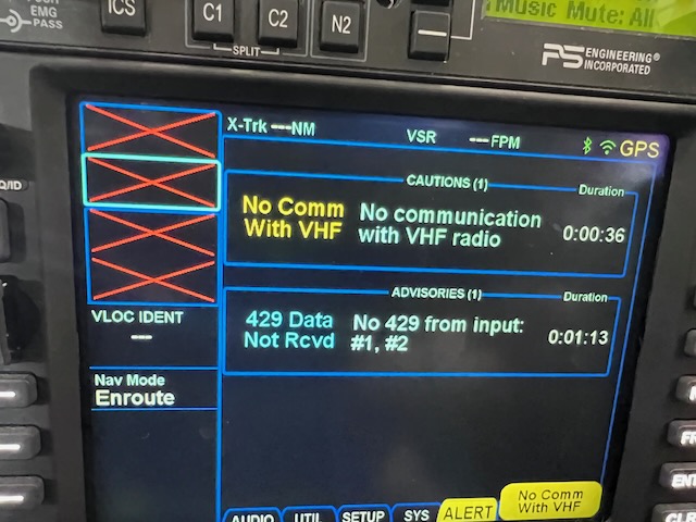 |
|
 |
|
|
Melohn
Senior Member 

Joined: 11 Dec 2013 Location: PHNL Status: Offline Points: 124 |
Post Options
Thanks(0)
Quote Reply
Posted: 22 Jan 2024 at 1:33pm |
|
I’m pretty sure you’ll find that LAC avionics could bench test this for you.
That said, I’d probably send it in, particularly if it’s still under warranty. |
|
|
|
|
vas4avidyne
Groupie
Joined: 21 Jun 2022 Location: SF Bay Area Status: Offline Points: 50 |
Post Options
Thanks(0)
Quote Reply
Posted: 22 Jan 2024 at 1:52pm |
|
Thanks, Bill! Unfortunately, the unit is no longer under warranty :-(!
Thanks for the pointer to LAC Avionics. I tried calling the number for them but it gets disconnected right away. I tried sending them an email but it bounced. If you have another ways to contact them, please do let me know. I did get a pointer from Avidyne to a dealer called NorCal Avionics in Watsonville so i have left them a message.
|
|
|
|
|
keithrkoenig
Newbie 
Joined: 16 Nov 2021 Location: Byron C83 Status: Offline Points: 19 |
Post Options
Thanks(0)
Quote Reply
Posted: 23 Jan 2024 at 4:01pm |
|
You say the first shop tested the power and it was ok, Is that to the pins in the rack? Did someone power it up on the bench? Mine will do that when I have only the large connector connected on my desk using the lone star docking station. Once I wired up the other connector, to upgrade to 10.3, it all works as it has power to the com board.
|
|
|
|
|
eallevato
Groupie
Joined: 04 Apr 2018 Location: Northridge, CA Status: Offline Points: 69 |
Post Options
Thanks(0)
Quote Reply
Posted: 23 Jan 2024 at 4:21pm |
|
You should have 2 circuit breakers for the install.
The first is a 10 Amp c/b dedicated to the COMM portion of the IFD. The second c/b should be a 5 Amp for the GPS/Nav portion. Some folks wire in only one c/b for both. Gene
|
|
|
Gene
|
|
|
|
|
vas4avidyne
Groupie
Joined: 21 Jun 2022 Location: SF Bay Area Status: Offline Points: 50 |
Post Options
Thanks(0)
Quote Reply
Posted: 23 Jan 2024 at 4:40pm |
|
Keith, The first shop was an avionics tech who came over to my plane. We pulled the IFD unit out and with a multimeter, he checked the power and ground on the pins on the 1002 connector (where were fine). It was not done on the bench.
Gene, I bought this RV-10 in 2022 and it (unfortunately) didn't come with a wiring diagram. This tech and I looked at the circuits and it does look like both of them are wired into the 10A COMM portion. The strange part is there were pins on the side that connects to the IFD for the power on the 1006 connector (the 2A circuit) and they didn't have power but when we disassembled the back of the cage, it turned out that it was a false alarm because there were no wires to those pins on the back side. So, the next step is to bench test it at an Avidyne shop this Saturday and if it fails there, it will need to be shipped back to Avidyne for repair :-(. Thanks, Vas
|
|
|
|
|
eallevato
Groupie
Joined: 04 Apr 2018 Location: Northridge, CA Status: Offline Points: 69 |
Post Options
Thanks(0)
Quote Reply
Posted: 23 Jan 2024 at 11:47pm |
|
The NAV/GPS power comes into P1001, not P1006 as you stated.
Gene
|
|
|
Gene
|
|
|
|
|
vas4avidyne
Groupie
Joined: 21 Jun 2022 Location: SF Bay Area Status: Offline Points: 50 |
Post Options
Thanks(0)
Quote Reply
Posted: 24 Jan 2024 at 12:25am |
|
Ok, thanks. I thought Avidyne Support pointed me to pin 44 on P1006 (in addition to pins 11 and 12 on P1002). What would that be for?
As you mention, it looks like pins 77 & 78 provide power to P1001. Does this provide power to the VLOC subsystem also or just GPS? Thanks, Vas
|
|
|
|
|
eallevato
Groupie
Joined: 04 Apr 2018 Location: Northridge, CA Status: Offline Points: 69 |
Post Options
Thanks(0)
Quote Reply
Posted: 24 Jan 2024 at 11:06am |
|
Pins 77 and 78 on P1001 are NOT power, those pins are ground. Pin 44 of P1006 is only used IF an instrument requires the VOR/LOC and Glideslopte Superflags. In all of the GA installs that I have done, I have never used pin 44 of P1006. Since your RV is a 12 Volt system, here is a summary of what you should have: P1001 (78 pins): Pins 19 and 20: 12 Volt power coming in from a 7.5 Amp circuit breaker to provide power to the GPS and NAV circuitry. The main wire should be an 18 AWG wire that gets split into two 22 AWG wires to the actual pins. Pins 77 and 78: Airframe ground, or the negative side of the battery. The main wire should be an 18 AWG wire that gets split into two 22 AWG wires to the actual pins. P1002 (25 pins): Pins 11 and 12: 12 Volt power coming in from a 10 Amp circuit breaker to provide power to the COMM circuitry. The main wire should be an 18 AWG wire that gets split into two 20 AWG wires to the actual pins. Pins 21 and 22: Airframe ground, or the negative side of the battery. The main wire should be an 18 AWG wire that gets split into two 20 AWG wires to the actual pins. That is it. Gene
Edited by eallevato - 24 Jan 2024 at 11:08am |
|
|
Gene
|
|
|
|
|
vas4avidyne
Groupie
Joined: 21 Jun 2022 Location: SF Bay Area Status: Offline Points: 50 |
Post Options
Thanks(0)
Quote Reply
Posted: 24 Jan 2024 at 12:14pm |
|
Thanks, Gene! After looking at your list, I realized that I had mistyped the pin numbers for power on P1001! I am pretty sure the tech did not check the power on the P1001 pins so I can plan to do that when I go to the plane next.
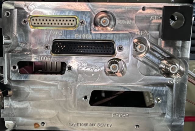
I can't seem to find the pin diagram in the manual or on in internet. What is the pin numbering logic for P1001 in the photo below? Or more specifically, which ones are pins 19, 20, 77 and 78? Thanks, Vas
 |
|
|
|
|
vas4avidyne
Groupie
Joined: 21 Jun 2022 Location: SF Bay Area Status: Offline Points: 50 |
Post Options
Thanks(0)
Quote Reply
Posted: 24 Jan 2024 at 1:15pm |
|
I checked with the tech and he indicated that he did check the power and ground pins on P1001 also so I guess that doesn't seem likely to be the problem either. Oh, well!
The next step is for the unit to be bench tested on Saturday - that should provide a good path forward.
Thanks, Vas |
|
|
|
|
vas4avidyne
Groupie
Joined: 21 Jun 2022 Location: SF Bay Area Status: Offline Points: 50 |
Post Options
Thanks(0)
Quote Reply
Posted: 01 Feb 2024 at 7:58pm |
|
The follow up on this issue is that I took it an Avidyne shop at KWVI and it didn't come up on the bench (they indicated it was likely because of excessive current draw) so it looks like the issue was with the unit after all so it has been shipped back to Avidyne for repair.
Thanks for all the suggestions. Vas
|
|
|
|
|
Post Reply
|
|
 Tweet
Tweet
|
| Forum Jump | Forum Permissions You cannot post new topics in this forum You cannot reply to topics in this forum You cannot delete your posts in this forum You cannot edit your posts in this forum You cannot create polls in this forum You cannot vote in polls in this forum |


 Topic Options